
In this project, home appliances can be controlled from anywhere via internet with help of Arduino and ESP8266. This gives brief guideline for working with ESP8266 and Arduino to make the system for
Internet of Things.
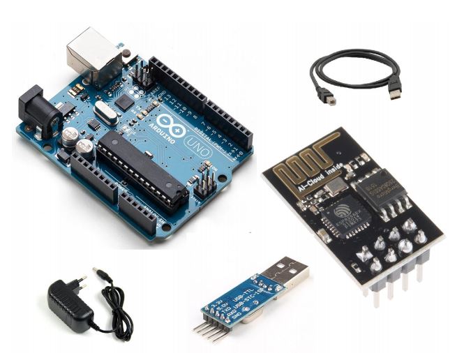
1. Hardware Accessories List:
1. Arduino UNO Board
2. ESP8266 Module
3. Arduino Compatible USB cable (Type A to Type B USB Cable )
4. USB To RS232 TTL Chip Converter Adapter Module
5. 12V/1A DC jack power adapter
 |
Required Hardware |
2. Required Software
1. Arduino IDE
2.Webpage from www.thingspeak.com
 |
Webpage from thingspeak |
3. ESP8266 Module
The ESP8266 WiFi Module is a self contained SOC with integrated TCP/IP protocol stack that can give any micro-controller access to your WiFi network.
3.1 Pin Diagram:
 |
ESP8266 |
1. GND 2. TX 3. GPIO 1 4. CH_PD 5. GPIO_0 6. RST 7. RX 8. VCC
3.2 Connections:
VCC ---> 3.3V
CH_PD ---> 3.3V
TX ---> RX PIN OF THE ARDUINO
RX ---> TX PIN OF THE ARDUINO
>>With help of USB-TTL converter sending AT command from PC to ESP8266 Module for Testing
and Setup via Serial Monitor.
>>Just follow the below At commands.
3.3 List of AT Commands:
1. AT – Attention
It returns O.K Means Device is working good.
2. AT+GMR
Current Firmware Version
3. AT+RST
Reset The Device
4. AT+CWMODE=
4. Webpage Creation
4.1 Thingspeak
ThingSpeak is an open source “Internet of Things” application and API to store and retrieve data from thingspeak using HTTP over the Internet or via a Local Area Network.
>> First, to create your own account with Thingspeak website.
>> Then, you will find some option from that APPS tab like..
1. Talkback
2. ThingHTTP
3. React
4. ThingTweet
5. TweetControl
6. TimeControl
>> The above listed option..we will choose Talkback.
 |
Talkback option |
>> The above image. You have to give name after that, click add command option to give your own
command.
>> Then we need to create a webpage like the below image. For that need to use the Plugin option from Thingspeak.
>> Click plugin option new --->Custom (no starter code) . After this some window will open there you can type the source code. As like your webpage wants to be.If you want to make some style, you will use CSS.
5. HTTP protocol initialization with Arduino coding and Webpage
HTTP functions as a request–response protocol in the client–server computing model.
5.1 Request methods are:-
1. GET
2. POST
3. HEAD
4. DELETE
5. PATCH
6. CONNECT
7. OPTIONS
8. TRACE
9. PUT
So, as mentioned above. We will be going to use only POST and GET methods to complete our task.POST:
1. It is used to send some commands to the server when the button on the website is pressed.2. We used this request at the website.
GET:
1. It is used to get the command from the server continuously.2. We used this request at our Arduino code.
6. Implementation
6.1 Configure the ESP8266 with Serial Monitor of Arduino
For Initial configuration of ESP8266 module we need to connect our ESP module to our PC via USB to TTL converter module.After that,TX of ESP Module ---> RX of USB to TTL converter
RX of ESP Module ---> TX of USB to TTL converter
3.3V VCC USB to TTL module ---> 3.3V VCC Pin of ESP Module
GND USB to TTL module --> GND Pin of ESP Module
Then, you may find some com port number from your PC. Open the Serial monitor from Arduino with same COM port as USB to TTL converter module has connected.
>> After that follow the below commands to configure your ESP module.
>> Open the Arduino software.
>> Then go to Serial monitor with ESP module COM port.
>> Give baudrate 9600. And Choose Both NL(New Line) and CR(Carriage Return)
 |
Settingup ESP |
7. Demo
Demo of our project
8.Conclusion
>> The above demo shows the working of the full project. Here, i turned on LED, which is inbuilt on the arduino. In your case, instead of LED, you can connect the 5V relay. That relay you can able to control all your AC loads (Home Appliances).
Thats all!!!!!😊😊😊😊
If you have any doubt on this, feel free to write in the command box....,
No comments:
Post a Comment